Reduction of Local Scour Around A Bridge Pier Using Triple Rectangular Plates
Alireza Pourzaker Arabani1 * and Human Hajikandi1
1
Department of Civil Engineering,
Islamic Azad University,
Central Tehran Branch,
Tehran,
Iran
http://dx.doi.org/10.12944/CWE.10.Special-Issue1.08
The performance of vertical triple plates as a new countermeasure in control of local scour around a cylindrical model pier is studied. Two ones of the plates are attached to the side wall one of the pier at one pier diameter distance, extending toward upstream distance and the third one is located in the middle, attached to the pier nose. All the three plates are parallel to flow direction. Experiments are conducted for five different depths of flow and two different lengths of the lateral plates, namely 8 and 14 cm. all the runs are performed under the clear water flow over uniform sediment. The results showed a maximum efficiency of 76% in scour reduction for 8 cm long side plates and 85% for 14 cm long ones.it is also found that the proposed setup act simultaneously as both the bed armoring and flow altering countermeasure.
Copy the following to cite this article:
Arabani A. P, Hajikandi H. Reduction of Local Scour Around A Bridge Pier Using Triple Rectangular Plates. Special Issue of Curr World Environ 2015;10(Special Issue May 2015). DOI:http://dx.doi.org/10.12944/CWE.10.Special-Issue1.08
Copy the following to cite this URL:
Arabani A. P, Hajikandi H. Reduction of Local Scour Around A Bridge Pier Using Triple Rectangular Plates. Special Issue of Curr World Environ 2015;10(Special Issue May 2015). Available from: http://www.cwejournal.org/?p=10553
Download article (pdf)
Citation Manager
Publish History
Introduction
Bridges are obviously vital elements in transportation. Their function during flood phenomenon is specifically important. Installation of piers across rivers alters the local flow field, which is usually accompanied by a sediment- carrying capacity that generally leads to formation of scour holes around the pier. The scour holes threaten the safety of bridge. In a study published by the federal highway administration (FWHA) it is expressed that among 383 bridges failure caused by floods, 25 percent involved pier damage and 75 percent involved abutment damage. Therefore, study on the control and prevention of scour hole around bridge pier is an important step in bridge design. There are two major countermeasure techniques available for the control of scour hole size at bridge piers, known as: (1) bed armoring countermeasure; also known as direct method. (2) Flow altering countermeasure or indirect method.
In the former the stream bed resistance is increased by application of physical barriers such as rip rap (Abd El-Razek, 2003). Among the numerous studies carried out on this category are (Yoon et al,1995), (Parola, 1993), (Worman, 1989), ( Chiew and Lim, 2000), ( Lauchlan and melville, 2001), in the latter group, the strength of the down flow and horseshoe vortex, which are the main causes of pier is decreased, (Parker et al, 1989), (Chiew and Lim, 2003), (tafarojnoruz et al, 2010), classified flow altering countermeasure in to four groups, on account of their shape and performance; (1) opening through piers, such as slot or internal connecting tubes. These configuration were studied by (Abd El-Razek et al, 2003), (Vital et al, 1994), (Grimladi et al, 2009), (Tanaka and Yano, 1967), (Heidarpour, 2003), (Moncada-Metal, 2009), studied the performance of internal connecting tubes and reported an efficiency of up to 39% for the most optimum configuration. (Vital et al, 1994), proposed application of piers groups instead of a massive pier to reduce flow disturbance and local scour. The countermeasure in this category is the slot. The slots divert the down flow through their opening and decreased the scour hole size. (Tanaka and Yano 1967), have reported that partially embedded slots into the bed have higher efficiencies. (Heidarpour et al, 2003), investigated the performance of slots located on groups of inline piers and concluded that their efficiency increase with decreasing the pier spacing and angle attack.
- Pier attachments, including threading (Dey et al, 2006), collar and horizontal plates, (Parker et al, 1998), (Kim et al, 2005), (Dargahi, 1987), (Sani khani et al, 2008), (Moncada-m, 2009), (Zarrati et al, 2004), (Zarrati et al, 2006), (Ghorbani and Kells, 2008). Another form of this countermeasure includes plates or vanes of different shapes. (Ghorbani and Kells, 2008), reported that vanes attached to the pier are effective in diverting flow from the vicinity of the pier and reducing the induced scour. (Maza, 1967), carried out the earliest study on pier attached plates. He used rectangular plates installed vertically and at an angle of attack with respect to the flow direction. He recommended the plates to be attached at a slope 3:1 to obtain the optimum performance. (Gupta, 1992), studied the performance of delta-wing plates attached to the pier along the axis of symmetry. (Diado and Yano, 1995) installed slanting plates on the upstream face of a circular plate and simultaneously attached a guide wall to the pier nose. They reported a maximum efficiency of 90% for their suggested setup.
- Bed attachment diverts to weaken the approach glow pattern. These devices comprise of sacrificial piles (Melville and Had field, 1999), (Chiew and Lim, 2003), vanes and sill (Odgaard and Wang, 1987), surface guide panels and sleeve and collared (Huang et al, 2005), (Grag et al, 2008), (Singh et al, 2001). The earliest study on sacrificial piles was carried out by (Chabert and Engeldinger, 1956). They installed piles in a triangular arrangement upstream of the pier. They reported maximum scour depth reducing of 50% for their best configuration. Application of submerged of piers turns back to the extensive studies (Odgaard and Wang, 1991). They showed that the flow circulation generated as a result of flow passing the vanes change the flow pattern and direction of bed stress and reduce scour size.
- Other devices such as implement of holes on the wall of the lower part of the pier to extract water by suction pump through the pier (Rooney and Machemehl, 1977). A number of studies have also reported the success of combined scour countermeasure in reducing scour hole size around the piers, such as the simultaneous of collar and rip rap (Zarrati et al, 2006), (Mashahir et al, 2010), slots and still (Grimaldi et al, 2009), collar and submerged vanes (Odgaards and Wang, 1987).
- Each of the above mentioned countermeasures is subject to some advantages and certain shortcoming. In summary: bed armoring countermeasure has some limitation in application in a wide range of field situation. Also, the difference in the efficiency of flow altering countermeasure reported up to now is too scattering, that requires further investigation considering the effect of various flow condition like presence of debris flow and live bed.
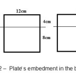
In this paper these rectangular plates are connected to the upstream face of a cylindrical pier in a collinear direction. Two ones of the plates are installed at one pipe diameter distance from each other on the two lateral sides of the pier and the third one is located along the centerline axis of the pier cross section. As seen in figure 2, three types of plates with different lengths are embedded up in the bed around 8 cm and faced with the stream above the substrate around 4 cm.
(a) 8 cm long side walls plates (b) 14 cm long side walls plates
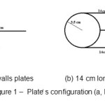 |
Fig. 1: PlateÌ› s configuration (a, b) Click here to View figure |
 |
|
The main motivation to introduce the aforementioned configuration as a new scour countermeasure was to employ a new structure for pier protection which simultaneously acted as bed armoring and also flow altering countermeasure. Hence prior to the main experiment a numerical code was developed to investigate the flow pattern around the pier with protective plates arranged as seen in figure 1. The numerical domain consisted of a 3-dimensional mesh in which the standard k-Æ turbulent model was utilized to simulate flow pattern around the pier. The numerical simulation expressed that application of plates significantly reduce the strength of horseshoe vortex and the down flow. Also the resistance due to the installation of side wall plates remove accelerated flow from near of pier thus, flow which hits to pier has not enough energy to form powerful scour mechanism.
 |
|
Materials and Methods
The effective parameters that influence the problem under considering are summarized in equation (1):
F (dp, y, g, u, lp,d50, Ïg, s0, ds )=0 (1)
Where F is a functional, dp and ds are the nominal diameter of the pipe and depth of scour respectively, y is the depth of flow above the bed layer and lp is the length of the side wall plates. U and g are the velocity and gravity acceleration respectively and s0 is the slope of the flume. Finally, d50 is the respectively sediment particle size from which 50% of the bed particles by weight are finer and Ïg is geometrical standard deviation of the sediment particles. All of the experiments were carried out in one type of soil. The bed slope was also constant in the experiments. Then by omitting the symbols s0 ,d50, Ïg from the list of effective parameters and performing the buckinghum-π dimensional analysis the following dimensionless parameters yield:
ds / y= F ( Fr , dp/y, lp/y ) (2)
With Fr= u/ (gy)0.5 the Froude number.
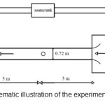
The experiments were carried out in an 8m long, 0.72m wide and 0.5m deep, Plexiglas-sided flume. The model pier was made of iron with a nominal diameter of 0.07m and a length of 0.4m. According to (Chiew and Melville, 1987) the maximum pier diameter has to be restricted to 10% of channel width so that the effect of flume sidewalls on scour depth becomes negligible. Pier is located 3m downstream from the flume entrance to provide the condition of fully developed flow. The thickness of the sediment recess was 0.25m. The sediment particles had a mean diameter d50 = 0.72mm and a geometric standard deviation of Ïg= 1.2, which satisfied the condition of uniform sediment gradation. Also according to (Raudkivi and Ettema, 1983) for non-ripple forming sediments (d50 ≥0.7mm) and dp / d50 (dp: pier diameter and d50: diameter of bed material) was more than 50 (dp/d50=97) the effect of sediment size on the scour hole becomes negligible. The clear water flow condition exist up to u*=0.95u*c, where u* is the shear velocity and u*c is the critical shear velocity obtained from the shields diagram.
Before starting the main test it was essential to find threshold of sediment motion. Some researchers (Day, 2001) and (Day and Kumar, 2002) investigated the incipient motion of sediment particles and proposed different empirical formulas to account for bed material motion. In the current paper, the threshold of bed material motion was determined by observation of particle motion in the flume before the installation of piers. The procedure was achieve a condition that in which the finer bed particles moved and the bed elevation reduced about 2 to 3mm during the experiment run. The test stated within the limit of present work, when the depth of flow is 0.18m and inflow discharge is 0.092 m3/s, the bed is at incipient motion. Then, during all different experimental runs, the ratio of shear velocity calculated from the depth of flow and energy to the critical shear velocity obtained from shields diagram was about 0.9.
 |
|
Table 1 show the initial condition implemented in difference experimental runs. The inflow discharge was measured by a turbine flow meter connected to the wall of the inlet pipe. The calculated error for the range of discharge applied in present work (40 l/s
Table1: Summary of experiments
|
test number |
pier condition |
lateral plates() |
middle plate() |
time(min) |
discharge(lit/sec) |
|
1 |
single |
- |
- |
180 |
40 |
|
2 |
single |
- |
- |
180 |
53 |
|
3 |
single |
- |
- |
180 |
66 |
|
4 |
single |
- |
- |
180 |
80 |
|
5 |
single |
- |
- |
180 |
92 |
|
6 |
protected |
8×12 |
12×12 |
180 |
40 |
|
7 |
protected |
8×12 |
12×12 |
180 |
53 |
|
8 |
protected |
8×12 |
12×12 |
180 |
66 |
|
9 |
protected |
8×12 |
12×12 |
180 |
80 |
|
10 |
protected |
8×12 |
12×12 |
180 |
92 |
|
11 |
protected |
14×12 |
12×12 |
180 |
40 |
|
12 |
protected |
14×12 |
12×12 |
180 |
53 |
|
13 |
protected |
14×12 |
12×12 |
180 |
66 |
|
14 |
protected |
14×12 |
12×12 |
180 |
80 |
|
15 |
protected |
14×12 |
12×12 |
180 |
92 |
The plates were embedded up to more than their half in all the experiments. Then the depth of the plates under the bed layer at the beginning of each test was 8cm. previous experiments on scour around piers have proved that scour phenomenon is too time consuming. The time for achieving equilibrium state around piers, within the limit of present work, is around 12-15 hours. After finishing each test the scour geometry was measured by means of a liminimeter. It was a point gauge with an accuracy of ±0.01 mm which was mounted on a traveling carriage. The longitudinal and transverse motion of the point gauge was read by two scaled rulers connected to the carriage. The rulers provide reading longitudinal and transverse scales with an accuracy of ± 0.1cm.
The main experiments were carried out in three phases, at first phase of the experiments, the scour geometry around pier without any countermeasure was obtained. After 180 minutes, the pump was stopped and the water was dredged gradually out of the flume by means of a valve provided in the flume bottom for drainage, then the scour profile was measured by the liminimeter. In the second phase of the experiments, two 8cm long plates were installed parallel to the flow direction and 12cm long plate was used along the center line axis. Finally in the third phase of the experiment the side wall plates were substituted by 14cm long ones and the same procedure of phase 2 was repeated.
Results
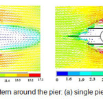
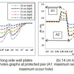
It is been seen in figure 5 (a, b) plates installation due to considerable scour decrease at the face of upstream of pier and particularly at sides and back area of the pier sedimentation is occurred. In various investigations sedimentation is not occurred around the pier but in this study, alignment level behind of the pier increases even more than first level of the experiment.
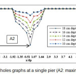
As seen by increasing the inflow discharge or depth of flow, scour holes become deeper, the maximum scour depth occurs at the vicinity of the pier nose. By comparison of the scour graph of figure 5 and 6 it is found that the plates significantly alter the flow pattern at the lee side of the pier and instead of scouring as observed in single pier. (X: axial distance of pier, ds: scour depth, dp: pier diameter)
 |
|
 |
|
It is also observed that by increasing the lengths of the lateral plates from 8 to 14 cm, the scour size at the front of pier is decreased.
Table 2: The ratio of the scour depth (ds) at the front of pier to the pier diameter (dp)
|
Test Number |
Pier condition |
Lateral plates(cm2) |
Middle plates(cm2) |
Time (min) |
Discharge (lit/s) |
Depth (m) |
ds/dp |
|
1 |
Single |
- |
- |
180 |
40 |
10 |
0.8571428 |
|
2 |
Single |
- |
- |
180 |
53 |
12 |
0.9142857 |
|
3 |
Single |
- |
- |
180 |
66 |
14 |
0.9385714 |
|
4 |
Single |
- |
- |
180 |
80 |
16 |
0.9542853 |
|
5 |
Single |
- |
- |
180 |
92 |
18 |
0.9971428 |
|
6 |
Protected |
8×12 |
12×12 |
180 |
40 |
10 |
0.2785714 |
|
7 |
Protected |
8×12 |
12×12 |
180 |
53 |
12 |
0.3214285 |
|
8 |
Protected |
8×12 |
12×12 |
180 |
66 |
14 |
0.5285714 |
|
9 |
Protected |
8×12 |
12×12 |
180 |
80 |
16 |
0.5685714 |
|
10 |
Protected |
8×12 |
12×12 |
180 |
92 |
18 |
0.5685713 |
|
11 |
Protected |
14×12 |
12×12 |
180 |
40 |
10 |
0.2571428 |
|
12 |
Protected |
14×12 |
12×12 |
180 |
53 |
12 |
0.2928576 |
|
13 |
Protected |
14×12 |
12×12 |
180 |
66 |
14 |
0.3928575 |
|
14 |
Protected |
14×12 |
12×12 |
180 |
80 |
16 |
0.4357146 |
|
15 |
Protected |
14×12 |
12×12 |
180 |
92 |
18 |
0.4785714 |
The implement of plates at the upstream face of the pier wall has two important effects on scour process:
- The flow pattern as indicated in the numerical simulation changes, the approaching flow velocity near the base of the pier is divided into two branches. Hence a less sever down flow is generated and consequently a weaker horseshoe vortex is produced. Also the lateral length of the plates and their flat shape effectively reduce the negative pressure induced by the round shape of the side walls of the pier. This effect is accompanied by a weaker wake and a decreased area of the zone at downstream location.
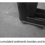
- (2) The plates confine the sediment and act as lateral barrels. They increase the stability of the particles against incipient motion and behave like bed armoring materials.
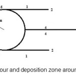
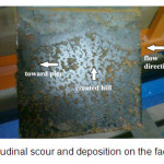
In figure 7 the different scouring and sedimentation zones are classified by numbers. In zone 2and 3 at the nose of the plates, local scouring is observed. The sediment particles are transferred from these zones toward downstream areas, namely zones 4 and 1. Observation of scour on the fact of the middle plate indicate that the scoured particles at the vicinity of the plates nose generate a deposition hill with a steep slope at zone 4 which is continued by a milder slope from the hill crest toward the upstream face of the pier (figure 9). It is found that the particles dumped in zone 4 due to deposition. Gradually fill scour produced as a result of the horseshoe vortex at the upstream face of the pier. In zone 5 and 6 deposition process is observed. (figure8)
 |
|
 |
|
 |
|
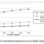
Figure 10 shows the variation of normalized maximum scour depth (ds/y) versus the Froude number. As seen by increasing the Froude number the maximum scour depth increases. Also it is observed that installation of the aforementioned countermeasure significantly reduces the maximum scour depth. The results indicate that the second configuration with longer side wall plates is more effective in scour protection.
 |
|
Discussion
Extensive numerical and experimental investigation on the performance of the triple rectangular protective plates installed at the upstream face of the pier wall parallel to the flow is conducted. The results indicate that the plates act simultaneously as both bed armoring and flow altering countermeasure. Qualitative result indicates that the aforementioned configuration is successful in both the down-flow currents generated as a result of increased static pressure of the flow at the upstream face of the pier and also the lee wake vortex formed as a result of flow separation at side walls of the pier. Quantitative results indicate that when the length of the lateral plates and middle plate are (1.14 dp) and (1.714 dp) respectively the maximum scour depth reduces considerably. The data shows a 76% reduction in maximum scour depth for 8cm long side wall plates and 85% for 14cm long side wall plates.
References
- Abd EL-Razek, M. A. E.-M. M. M. (2003), “Scour reduction around bridge piers using internal openings through the pier”, Thessaloniki, C2, Proc. 30 IAHR Congress, pp. 285-292.
- Parola, A. (1993) “Stability of riprap at bridge piers”, J. Hydraulic. Engng., Volume 119, pp. 1080-1093.
- Chiew, Y.M, Lim,S.Y. (2003) “Protecting of bridge piers using a sacrificial sill”, S. l., Proc. ICE water, maritime and energy
- Tafarojnoruz, A. (2010) “Flow altering countermeasures against scour at bridge piers”, J. Hydraulic Research, 48(4), pp. 202-209.
- Vittal, n. U. H. M (1994) “Clear water scour around bridge pier”, J. Hydraulic Engng., 120(11), pp. 1309-1318.
- Tanaka, S. Y. (1967) “Local scour around circular cylinder”, Fort Collins, co, 3, Proc. 12th IAHR Congress, pp. 125-134.
- Heidarpour, M. (2003) “Control and reduction of local scour at bridge pier groups using slots”, Thessaloniki, Proc. 30th IAHR Congress, pp. 301-307.
- Moncada-M., A. P. (2009) “Scour protection of circular bridge piers with collars and slots”, J. Hydraulic Res., 47(1), pp. 119-126.
- Dey, S. (2006) “Control of scour at vertical circular piles under waves and current”, J. Hydraulic Engng., 132(3), pp. 270-279.
- Parker, G. Toro-Scobar, C. (1998) “Countermeasures to protect bridge piers from scour”, Washington, DC: Final report NCHRP project 24-7. Transportation research board.
- Kim, U. Kim, J. Hahm, C. (2005) “Scour countermeasure using additional facility in front of bridge pier”, Seol. 31th IAHR Congress, pp. 5823-5829.
- Dargahi, B. (1987) “Flow field and local scouring around a cylinder”, Royal Institute of Technology, Stockholm S., Volume Bulletin 137.
- Zarrati, A. (2004) “Application of collar to control scouring around rectangular bridge pier”, J. Hydraulic Res., 42(1), pp. 97-103
- Zarrati, A. (2006) “Reduction of scour in the vicinity of bridge pier groups using collar and riprap”, J. Hydraulic Engng., 132(2), pp. 154-162.
- Ghorbani, B. (2008) “Effect of submerged vanes on scouring at a cylindrical pier”, J. Hydraulic Res., 46(5) pp. 610-619.
- Gupta, A. (1992) “Local scour reduction by a Delta-Wing like passive device”, Pune, Proc. 8th APD-IAHR Congress, pp. B471-B481.
- Melville, B. (1999) “Use of sacrificial piles as pier countermeasures”, J. Hydraulic Engng., 125(1), pp. 121-1224.
- Odgaard, A. W. Y. (1987) “Scour prevention at bridge pier”, VA, Proc. Nalt. Conf. Hydraulic Engineering, Williamburg.
- Mashahir, M. Z. A. E. (2010) “Application of riprap and collar to prevent scouring around rectangular bridge piers”, J. Hydraulic Engng., 136(6), pp. 183-187.
- Chiew, Y. M. (1987) “Local scour around bridge piers”, J. Hydraulic Res., 25(1), pp. 15-26.
- Raudkivi, A. (1983) “Clear water scour at cylindrical piers”, J. Hydraulic Engng., 109(3), pp. 338-350.
- Dey, S. (2002) “Initiation of shell motion on sand beds: An experimental study”, International J. Sediment Research, 17(4), pp. 270-279.